Free electron model of metals
“ Freedom's just another word for nothing left to lose. ” - Janis Joplin
| ||||||
The free electron model is a simple model for the behavior of valence electrons in a crystal structure of a metallic solid. It was developed principally by Arnold Sommerfeld who combined the classical Drude model with quantum mechanical Fermi-Dirac statistics. Given its simplicity, it is surprisingly successful in explaining many experimental phenomena, especially
- the Wiedemann-Franz law which relates electrical conductivity and thermal conductivity;
- the temperature dependence of the heat capacity;
- the shape of the electronic density of states;
- the range of binding energy values;
- electrical conductivities;
- thermal electron emission and field electron emission from bulk metals.
The free electron model assumes that the electrons in a metal behave like a gas of free particles. The removal of the valence electrons from an atom leaves a positively charged ion core. The free electron model assumes that the charge density associated with the ion cores is spread uniformly throughout the metal so the electrons move in a constant electrostatic potential.
Classical Electron Model
Drude transport theory
The Drude theory assumes that movement of electrons can be described classically. The model resembles a pinball machine where the electrons accelerate, hit a scattering surface (positive ion), and then begin accelerating once more.
During the acceleration phase the velocity gained by the electron is described as:
Failed to parse (SVG (MathML can be enabled via browser plugin): Invalid response ("Math extension cannot connect to Restbase.") from server "https://wikimedia.org/api/rest_v1/":): {\displaystyle \Delta v = at = -\frac{eE}{m}t}
This gives the electron a total velocity
Failed to parse (SVG (MathML can be enabled via browser plugin): Invalid response ("Math extension cannot connect to Restbase.") from server "https://wikimedia.org/api/rest_v1/":): {\displaystyle v = v_{0} + \Delta v\!}
Then the electron scatters off a surface. The distance between scattering surfaces is called the mean free path, Failed to parse (SVG (MathML can be enabled via browser plugin): Invalid response ("Math extension cannot connect to Restbase.") from server "https://wikimedia.org/api/rest_v1/":): {\displaystyle l} .
Note that on average Failed to parse (SVG (MathML can be enabled via browser plugin): Invalid response ("Math extension cannot connect to Restbase.") from server "https://wikimedia.org/api/rest_v1/":): {\displaystyle v_0} is equal to zero since the movement is in completely random directions. So now we can calculate the average total velocity to be
Failed to parse (SVG (MathML can be enabled via browser plugin): Invalid response ("Math extension cannot connect to Restbase.") from server "https://wikimedia.org/api/rest_v1/":): {\displaystyle <v>\ =\ < v_0 + \Delta v >\ =\ <v_0> + <\Delta v>\ =\ <\Delta v>\!}
Failed to parse (SVG (MathML can be enabled via browser plugin): Invalid response ("Math extension cannot connect to Restbase.") from server "https://wikimedia.org/api/rest_v1/":): {\displaystyle <\Delta v>\ \sim \overrightarrow{E}}
Now using the equation for current
Failed to parse (SVG (MathML can be enabled via browser plugin): Invalid response ("Math extension cannot connect to Restbase.") from server "https://wikimedia.org/api/rest_v1/":): {\displaystyle \overrightarrow{j} = -ne<v> = -ne<\Delta v>\ = -\frac{ne^{2}}{m}<t>}
Here Failed to parse (SVG (MathML can be enabled via browser plugin): Invalid response ("Math extension cannot connect to Restbase.") from server "https://wikimedia.org/api/rest_v1/":): {\displaystyle <t>} is the average time between collisions, which is called the scatter time, Failed to parse (SVG (MathML can be enabled via browser plugin): Invalid response ("Math extension cannot connect to Restbase.") from server "https://wikimedia.org/api/rest_v1/":): {\displaystyle \tau} .
This gives us the Drude formula ,
Failed to parse (SVG (MathML can be enabled via browser plugin): Invalid response ("Math extension cannot connect to Restbase.") from server "https://wikimedia.org/api/rest_v1/":): {\displaystyle \sigma = -\frac{ne^{2}}{m}\tau} , where Failed to parse (SVG (MathML can be enabled via browser plugin): Invalid response ("Math extension cannot connect to Restbase.") from server "https://wikimedia.org/api/rest_v1/":): {\displaystyle \tau = \frac{l}{v_0}} , and Failed to parse (SVG (MathML can be enabled via browser plugin): Invalid response ("Math extension cannot connect to Restbase.") from server "https://wikimedia.org/api/rest_v1/":): {\displaystyle \sigma} is conductivity.
And from E&M recall that the resistivity of the material is:
Failed to parse (SVG (MathML can be enabled via browser plugin): Invalid response ("Math extension cannot connect to Restbase.") from server "https://wikimedia.org/api/rest_v1/":): {\displaystyle \rho = \frac{1}{\sigma} }
Also another often quoted value is the mobility, the proportionality constant between the velocity of the electrons and the electric field it is placed in, of the material which is:
Failed to parse (SVG (MathML can be enabled via browser plugin): Invalid response ("Math extension cannot connect to Restbase.") from server "https://wikimedia.org/api/rest_v1/":): {\displaystyle \mu = \frac{e\tau}{m_e} = \frac{\sigma}{ne} }
Hall effect
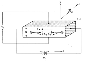
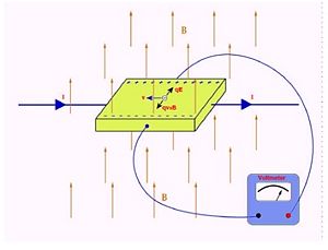
The Hall effect can illustrate what happens when current flows through a conductor within a uniform magnetic field. Some of the useful pieces of information the Hall effect can give us is the current density, the strength of the magnetic field, and the Hall Coefficient which will be discussed later. The Setup of the device is crucial to the understanding, so a picture has been provided to help illustrate how the Hall effect works.
For the ease of understanding a square piece of material has been chosen. This conducting material can be a metal or a semiconductor. We will start by applying a voltage so the right side is positively charged. As we know current will flow from positive to negative. This will have the current coming in from the right hand side. The charge of a particle determines the direction it will flow. Electrons as we know flow from negative to positive, so the electrons will flow in the opposite direction of the current. Conversely positively charged ions will flow in the same direction. Now we will apply a uniform magnetic field in the positive z direction. In order to understand how this magnetic field effects the electrons we will have to introduce the Lorentz Force.
Failed to parse (SVG (MathML can be enabled via browser plugin): Invalid response ("Math extension cannot connect to Restbase.") from server "https://wikimedia.org/api/rest_v1/":): {\displaystyle \vec{F_{L}} = -q \cdot ( \vec{v_{D}} \times \vec{B}) }
Looking at the Lorentz force we can see, by definition of the cross product, a perpendicular vector(the force) will be produced. Due to the symmetry of the square conductor we chose, the Lorentz force will be directed in the y direction allowing us to simplify our equation.
Failed to parse (SVG (MathML can be enabled via browser plugin): Invalid response ("Math extension cannot connect to Restbase.") from server "https://wikimedia.org/api/rest_v1/":): {\displaystyle \ \vec {F_{Ly}} = -q \cdot \vec{v_{D}} \cdot \vec{B} }
We simplify this further as the drift velocity of the particles is the mobility of the particle times the strength of the parallel electric field.
Failed to parse (SVG (MathML can be enabled via browser plugin): Invalid response ("Math extension cannot connect to Restbase.") from server "https://wikimedia.org/api/rest_v1/":): {\displaystyle \ \vec {F_{Ly}} = -q \cdot \mu \cdot \vec{E_{x}} \cdot \vec{B} }
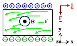
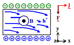
As described earlier we will have a fore acting on the particles at right angles to the velocity. Electrons moving from left to right will then collect themselves on one side of the surface of the conducting material while positive charges will move to the other side. The opposite is true when the carriers become positive ions instead of electrons. They will collect themselves on the opposite side of the conductor and so will the negative charges. When we have a potential difference like this, an electric field will be produced between both sides of the conductor. The following image helps picture what we are referring to. Keep in mind that this current is moving in the opposite direction as we initially started with.
A few very important things to point out. First, as you can see the direction of the Lorentz force did not change which is interesting but makes complete sense. If we look back to our equation, in order to replace an electron with a positive ion we would have to change two things. The first would be the charge of the particle making out "q" positive. We would also have to change the direction of the drift velocity. This will then cancel out any changes made. The other important face to point out is that the electric field produced by the opposite charges collecting on the sides of the conductor will oppose the Lorentz force. Eventually an equilibrium point will be reached in with the force of the electric field will equal that of the Lorentz force. Setting these equal we have:
Failed to parse (SVG (MathML can be enabled via browser plugin): Invalid response ("Math extension cannot connect to Restbase.") from server "https://wikimedia.org/api/rest_v1/":): {\displaystyle \ q \cdot \vec{E_{y}} = -q \cdot \mu \cdot \vec{E_{x}} \cdot \vec{B} }
Simplifying this expression we get:
Failed to parse (SVG (MathML can be enabled via browser plugin): Invalid response ("Math extension cannot connect to Restbase.") from server "https://wikimedia.org/api/rest_v1/":): {\displaystyle \ \vec{E_{y}} = -\mu \cdot \vec{E_{x}} \cdot \vec{B} }
Now we can find what is referred to as the Hall voltage.
We can take the electric field Failed to parse (SVG (MathML can be enabled via browser plugin): Invalid response ("Math extension cannot connect to Restbase.") from server "https://wikimedia.org/api/rest_v1/":): {\displaystyle \ \vec{E_{y}}} and multiply it by the depth of the material in the y direction and get the following equation.
Failed to parse (SVG (MathML can be enabled via browser plugin): Invalid response ("Math extension cannot connect to Restbase.") from server "https://wikimedia.org/api/rest_v1/":): {\displaystyle \ V_{H} = \vec E_{y} \cdot d}
We can now define another important parameter called the Hall coefficient.
Failed to parse (SVG (MathML can be enabled via browser plugin): Invalid response ("Math extension cannot connect to Restbase.") from server "https://wikimedia.org/api/rest_v1/":): {\displaystyle \ R_{H} = \frac{\vec{E_{y}}}{j \cdot \vec{B}}}
This means that the current density and the magnetic field are proportional to the Hall voltage define previously. It also important to point out the need for a number such as the Hall coefficient. If we look at the equation we can see that for identical and current densities and magnetic fields we will get different numbers for different metals or semiconductors. We can see that the Hall coefficient will change sign depending the charge of the carrier as well as allow us to calculate the mobility Failed to parse (SVG (MathML can be enabled via browser plugin): Invalid response ("Math extension cannot connect to Restbase.") from server "https://wikimedia.org/api/rest_v1/":): {\displaystyle \mu} .
Now the purpose of this device has not been discussed yet. Only the physics of the Hall effect has been shown. The effect allows us to create devices which help us read important pieces of information such as the magnetic field or the density of the carriers moving through a conductor.
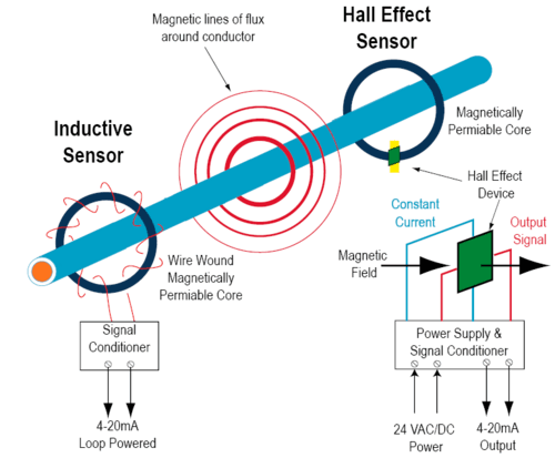
An example of such a device is the following. Thinking a conducting wire, when we send a current through the wire a proportional magnetic field will be produced around it. Around the wire, in the same way the magnetic field travels, is a magnetically permiable core a . A Hall sensor consist of this core, the Hall device, and circuitry. While the core wraps around the wire, the Hall device is placed in a small slit perpendicular to the magnetic field. A constant current is then applied to the device. Once the magnetic field interacts with the Hall device a potential difference is produced. This voltage can be measured and amplified giving back a current ratings. A picture of this setup can be found below.
These devices have a number of applications including speed detection, current sensing, and positioning. Some of the problems of using the Hall device is the amount of energy required to run the device as well as the limited range and high cost. Most are used to measure DC current.
Limitations of the classical electron model
Looking at the Drude model again and taking into account the Equipartition Theory:
Failed to parse (SVG (MathML can be enabled via browser plugin): Invalid response ("Math extension cannot connect to Restbase.") from server "https://wikimedia.org/api/rest_v1/":): {\displaystyle \frac{1}{2}mv_{0}^{2}=k_B T}
we can show that the scattering time should be proportional to Failed to parse (SVG (MathML can be enabled via browser plugin): Invalid response ("Math extension cannot connect to Restbase.") from server "https://wikimedia.org/api/rest_v1/":): {\displaystyle T}
Failed to parse (SVG (MathML can be enabled via browser plugin): Invalid response ("Math extension cannot connect to Restbase.") from server "https://wikimedia.org/api/rest_v1/":): {\displaystyle v_0 = \sqrt{\frac{2k_B T}{m}} \sim \sqrt{T}}
Failed to parse (SVG (MathML can be enabled via browser plugin): Invalid response ("Math extension cannot connect to Restbase.") from server "https://wikimedia.org/api/rest_v1/":): {\displaystyle \Rightarrow \tau \sim \frac{1}{\sqrt{T}}}
However, this is wrong since velocity is not proportional to Failed to parse (SVG (MathML can be enabled via browser plugin): Invalid response ("Math extension cannot connect to Restbase.") from server "https://wikimedia.org/api/rest_v1/":): {\displaystyle T} . When Failed to parse (SVG (MathML can be enabled via browser plugin): Invalid response ("Math extension cannot connect to Restbase.") from server "https://wikimedia.org/api/rest_v1/":): {\displaystyle T = 0} there is still quantum uncertainty.
Pauli Principle and Fermi-Dirac statistics
Fermi Dirac Probability Distribution
Failed to parse (SVG (MathML can be enabled via browser plugin): Invalid response ("Math extension cannot connect to Restbase.") from server "https://wikimedia.org/api/rest_v1/":): {\displaystyle f(E) = \frac{1}{e^{\frac{E-E_F}{k_B T}} +1} }
Schrodinger Equation for Free Electrons
Born-von Karaman boundary conditions
Fermi energy and Fermi momentum
Consider a cube of metal with sides Failed to parse (SVG (MathML can be enabled via browser plugin): Invalid response ("Math extension cannot connect to Restbase.") from server "https://wikimedia.org/api/rest_v1/":): {\displaystyle L} with faces perpendicular to x, y, and z axes. We must solve the time independent Schrodinger equation:
Failed to parse (SVG (MathML can be enabled via browser plugin): Invalid response ("Math extension cannot connect to Restbase.") from server "https://wikimedia.org/api/rest_v1/":): {\displaystyle -\frac{\hbar^2}{2m}\nabla^2 \psi = \epsilon \psi}
We can do this by imposing periodic boundary conditions such that:
Failed to parse (SVG (MathML can be enabled via browser plugin): Invalid response ("Math extension cannot connect to Restbase.") from server "https://wikimedia.org/api/rest_v1/":): {\displaystyle \psi(x + L, y + L, z+ L) = \psi(x,y,z)\!}
This gives us solutions of Schrodinger's equation are plane waves
Failed to parse (SVG (MathML can be enabled via browser plugin): Invalid response ("Math extension cannot connect to Restbase.") from server "https://wikimedia.org/api/rest_v1/":): {\displaystyle \psi(x,y,z) = \frac{1}{V^{\frac{1}{2}}} e^{i \mathbf{k} \cdot \mathbf{r}} = \frac{1}{V^{\frac{1}{2}}} e^{(k_x x + k_y y + k_z z)}}
where Failed to parse (SVG (MathML can be enabled via browser plugin): Invalid response ("Math extension cannot connect to Restbase.") from server "https://wikimedia.org/api/rest_v1/":): {\displaystyle V = L^3} and Failed to parse (SVG (MathML can be enabled via browser plugin): Invalid response ("Math extension cannot connect to Restbase.") from server "https://wikimedia.org/api/rest_v1/":): {\displaystyle V^{-\frac{1}{2}}} is to normalize the wave-function.
Maybe someone who has taken quantum can elaborate on the explanation above?' MatthewHoza 14:35, 29 April 2009 (EDT)
To satisfy the periodic boundary conditions the allowed wave-vectors must be:
Failed to parse (SVG (MathML can be enabled via browser plugin): Invalid response ("Math extension cannot connect to Restbase.") from server "https://wikimedia.org/api/rest_v1/":): {\displaystyle k_x = \frac{2\pi p}{L} \ \ \ k_y = \frac{2\pi q}{L} \ \ \ k_z = \frac{2\pi r}{L}}
where Failed to parse (SVG (MathML can be enabled via browser plugin): Invalid response ("Math extension cannot connect to Restbase.") from server "https://wikimedia.org/api/rest_v1/":): {\displaystyle p, q,} and Failed to parse (SVG (MathML can be enabled via browser plugin): Invalid response ("Math extension cannot connect to Restbase.") from server "https://wikimedia.org/api/rest_v1/":): {\displaystyle r} are integer values. This corresponds to an energy
Failed to parse (SVG (MathML can be enabled via browser plugin): Invalid response ("Math extension cannot connect to Restbase.") from server "https://wikimedia.org/api/rest_v1/":): {\displaystyle \epsilon = \frac{\hbar^2 k^2}{2m} = \frac{\hbar^2}{2m}(k_x^2 + k_y^2 + k_z^2)}
and a momentum
Failed to parse (SVG (MathML can be enabled via browser plugin): Invalid response ("Math extension cannot connect to Restbase.") from server "https://wikimedia.org/api/rest_v1/":): {\displaystyle \mathbf{p} = \hbar\mathbf{k} = \hbar(k_x, k_y, k_z)}

