Phy5645/Double pinhole experiment: Difference between revisions
No edit summary |
No edit summary |
||
| Line 3: | Line 3: | ||
-------- | -------- | ||
(a) As | (a) As stated in the problem, we assume that the denominators are approximately the same between the two waves. This is justified because the corrections are only on the order of <math>d/L\!</math>, and we are interested in the case where <math>d<<L\!</math>. We require that the numerators have the same phase, namely <math>kr_{+}-kr_{-}=2\pi n\!</math>. We expand the LHS with respect to <math>d\!</math>, | ||
:<math> | :<math> | ||
| Line 20: | Line 20: | ||
(b) Let us | (b) Let us work in units in which <math>k = 1</math>; that is, we measure all lengths in units of <math>1/k</math>. Then we pick ''d'' = 20, ''L'' = 1000. Here is the interference pattern. First along the ''y''-axis (''x'' = 0): | ||
Revision as of 10:31, 17 April 2013
Submitted by team 1
(a) As stated in the problem, we assume that the denominators are approximately the same between the two waves. This is justified because the corrections are only on the order of , and we are interested in the case where . We require that the numerators have the same phase, namely . We expand the LHS with respect to ,
Therefore,
and hence
(b) Let us work in units in which ; that is, we measure all lengths in units of . Then we pick d = 20, L = 1000. Here is the interference pattern. First along the y-axis (x = 0):
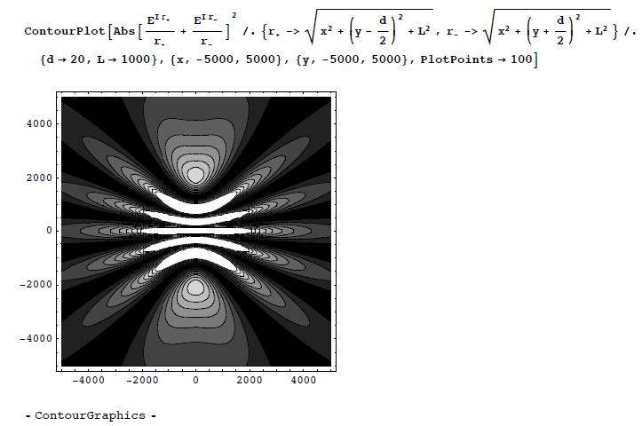
(c) Now on the plane:
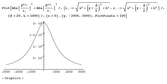
(d) For the same parameter as in (b), First along the y-axis (x = 0):
Now on the plane:
The main difference is the absence of the interference pattern.
Back to Stern-Gerlach Experiment


